2010年1月30日 星期六

Civil 3D Plan Projection Tools

Civil 3D有一項功能再2009版就已經提供出來了,但是過去筆者比較少研究,這功能成為Plan Production Tools(中文應該稱為"計畫出圖")。主要可以幫助使用者建立平、縱圖的設計成果出圖。

建立Plan Production Tools前,使用者一定要有樣版檔(*.DWT)這一個DWT需要包含出圖的設定,其中,圖紙大小設定、Viewport最為重要。
使用者一定要建立適當的圖紙,如A0,A1,A2,A3等圖紙,並且有計畫的將您慣用的圖框套用在Layout Space中的出圖範圍上。
之後,如果使用者要建立平、縱出圖的成果,請你建立兩個視埠(Viewport)並設定Viewport Type,如果要展示平面圖部分,請設定Viewport Type為Plan;若為縱斷面出圖,請設定Viewport Type為Profile。
當然在Annotation Scale、Standard Scale、Customer Scale中也需要依據出圖的比例作調整。這對後續出圖很有幫助。

然後至選單列選擇General->Plan Production Tools->Create View Frames...選項。
這主要是要幫助使用者建立平面圖的視埠範圍。
這功能相當好用,如果使用者的Alignment太長,View Frames會幫使用者自動切割範圍,分成很多當Sheets出圖。

系統開啟Create View Frames設定,這裡主要是設定"定線"與"定線要Layout"的範圍。

重點在Sheets中的設定,請使用者選擇你先前所建立的樣版檔,按下Template for Plan and Profile sheet:作設定。(因為要出圖的資料是包含平面與縱斷面,所以在Sheet Settings要選"Plan and Profile"

在Selct Layout as Sheet Template中,選擇你要出圖的比例。

接下來,設定你縱坡圖的樣式。筆者自己的樣版檔已經作好設定值,所以直接選定。這部分主要視建立縱斷面想要顯示的樣式與資料帶,因此如果使用者有樣版檔,就可以很輕鬆的出圖。

完成Create View Frames的設定後,系統會幫使用者建立View Frames。

緊接著,就可以開始利用Create Sheet功能開始出圖了。

再Create Sheets中,最重要的是選擇你已經建立好的View Frame Group。如果使用者有好幾個View Frame打算要出不同比例的圖紙,這時候就需要選定你的View Frames。

然後可以跳到Profile Views設定中設定Profile的資料。建議使用者適用Choose Settings來處理Profile的資料帶設定。

到Profile Setting 中,畫面跟一般建立Profile View一模一樣,所以直接去Bands設定資料內容。
PS:千萬不要以為跟筆者設定的一樣就會有相同的成果,筆者已經建立樣版檔了。
最後按下Finish,完成Create Muiltiple Profile Views設定,回到Create Sheet對話方塊,在按下Create Sheet就大功告成了!

計畫出圖成果。

操作心得:
1. Plan Production Tool的設定一定要有完整的樣板,不然一定會失敗。(如果要樣板檔,請寄信給我索取Mail to me。
2. 再設定過程中,最困難的是調整Scale,因為有出圖比例(Layout)、Profile View比例、標註比例,兩者會互相影響出圖成果,建議出圖比例以1:1000(一般AutoCAD設定);Profile View比例以你要出圖的Viewport要一致;標註比例最好也與Viewport比例一致。
3. 千萬多常是幾次,不要放棄,各程中你可以學習到很多Civil 3D的設定值,也慢慢可以成為Civil 3D的高階使用者。

2010年1月26日 星期二

Sharing Civil 3D and Revit Model in Google Earth

Today, I will share the Civil and Revit model on Google Earth. This is Engineering GIS demo for AEC.
There are some key points in this demo:
1. Both Civil 3D and Revit can post the model in Google Earth. So, it is AEC integration for Engineering GIS. And I have shared how to publishing C3D and Revit model to Google Earth already.
2. I had published Taipei City building in Google Earth, but the model is too large to be loaded in Google Earth.
3. In this case, I simulate flooding in Google Earth by different sea-level polygon. But it just a simulation for displaying.
4. Cause I lack the design data, so I just using the feature line object to build the channel model in Civil 3D.
5. Besides, I also try to publish the bridge and pier in Google Earth, it is very funny... If you want simulate the model of construction, you just need building it in CAD, and than you can see it by publishing by Civil 3D!


2010年1月18日 星期一

QGIS Convert CSV File to Shape File

Free GIS Software-QGIS also offer the function that can help Engineer to convert the CSV file with X, Y value to Shape file. The operations same as MapWindows GIS software.
As below, there are the screen capture of the QGIS. User can step by step to convert the CSV to Shapefile format.


MapWindows GIS Convert CSV File to Shape File

Most of Engineer get the X, Y value form site survey, something like collect the value form GPS. Today, I will share how to use MapWindow GIS(Free GIS software) to create the Shape File by CSV file.

1. Open the MapWindows GIS software, and click the "Converter->CSV to Shapefile".

2. The System will open the CSV to Shapefile Dialog, you can click the Browser icon form Input File.

3. Choose the CSV file and click "OK" for opening.

4. Click "Open File" and click "Point" for Data Type. Finally, click "Convert" to convert the CSV to Shapefile

5. You will see the Point data in the screen of MapWindows GIS.

Sharing Civil 3D 2010 Corridor Model (2)

Today, I will share some image of Civil 3D Corridor Model. In this project the key is create customerize Subassemibly, and Bridge design.


2010年1月7日 星期四

Sharing Civil 3D 2010 Corridor Model (1)

Today, I will share some photo of Civil 3D Corridor Model. In this project the key is create customerize Subassemibly, and mutli-link for grading.


2010年1月4日 星期一

CivilTech Plurk

Dear Reader,
I create a Plurk account named "CivilTech", Welcome to join CivilTech (http://www.plurk.com/CivilTech). CivilTech Plurk let you get the latest CivilTech news and learn tips of Engineering GIS more easily.

Best Regards,
CivilTech

2010年1月3日 星期日

Civil 3D Point Application "Import-Assign Elevation-Export"

本文教導使用者如何利用Civil 3D來匯入點位資料,並附與Google Earth地形資料的高程值,最後匯出成文字檔案。透過這一篇文章,讀者可以活用Civil 3D的點物件與Google Earth的地形資料。
In this article, you can learn how to use Civil 3D get the elevation data from Google Earth by Point Object. Besides, you can also learn the point data import/export.

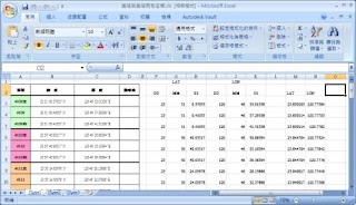
原始資料包含點編號、名稱、經緯度資料,但缺乏高程值。因此,利用Google Earth與Civil 3D來建立點物件的高程。The source data include the point number, name, latitude, and longitude data in Microsoft Excel file.
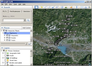
利用GAMINE GPS軟體MapSource查詢座標資料後,可以查出點位的高程(這不是很準確的方式,但是可以應急),另外也可以將成果發佈置Google Earth中來觀看結果,如下圖。I create a reference data by MapSource(The GAMINE GPS desktop software) and publish to Google Earth. In this step, we can locate the point in Google Earth, and then Civil 3D can download the surface from Google Earth.

筆者希望可以再利用點位資料找到Google Earth中的高程資料,來作一個驗證與比對。因此,這時候就利用到Civil 3D的軟體,但是如何自動將Google Earth高程值對應到點為呢?這一點就是本篇文章的一個重點了,筆者想到,這一種練習也許可以幫助使用者去學習如何活用Civil 3D這樣的軟體。

筆者的解決方式思考邏輯如下:
If you want achive the goal that get the elevation from Google Earth by Civil 3D Point Object, you need consider about the following things.
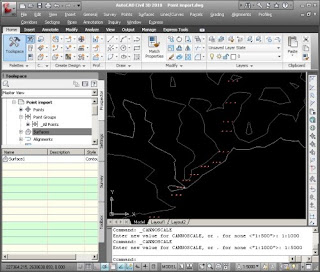
1. 利用Civil 3D可以開啟Google Earth的地形,如果我可以將點位在建立起來,這時候就會有地形與點位的資料了。How to create point object and overlap in Civil 3D? Civil 3D can import Google Earth Source and point file.
2. 點位建立,原始資料是經緯度的,Civil應開可以將點位轉換成TWD97,或將地形也轉換為TWD97的,這樣一來就可以套疊了。How to Tranfrom the source data CS from Lat/lon to TWD97? If the Google Earth surface and point data within the same CS, it's can overlapping.
3. Civil 3D因該可以將點位附與地形高程。(這部分需要測試)How to get elevation from surface by Civil 3D?
4. 筆者是否可以將資料匯出成對應的格式,提供比對。How to export?

綜上所述,筆者利用Civil 3D建立了一系列的操作,如下:
A.建立一個新的格式的點檔案格式。這一個格式是CSV檔案,主要用來匯入EXCEL資料(當然筆者有對格式修改過);然後,他要能夠將經緯度的座標系統轉換為TWD97的座標系統(因為筆者再匯入Google Earth的DWG專案檔已經設定為TWD97座標系統,且GE資料已經匯入)。First step is create a new Point File Format in Civil 3D to help you import the source data. in this step, I create a CSV input and set the CS to LL84.
注意:筆者設定經緯度讀取的資料格式為DECDEG Latitude與DECDEG Longitude

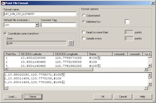
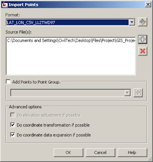
B.利用創建出來的點檔案格式讀取CSV檔案,這裡要注意的是要將下方的"Do Coordinate Transformation if Possible"勾選起來,這時候才會進行座標系統轉換。 When you import the point file, please click on the "Do Coordinate Transformation if Possible". Civil 3D will help you check the source data CS and current project CS and transform in the same CS automatically.

C.點位與地形套疊再一起了(由於Civil 3D匯入Google Earth地形資料的教學筆者以前文章已經發表過了,所以不再贅述)You can see the point date on the surface. I wont explain how to import Google Earth Surface by Civil 3D, cause we already discussed it before.

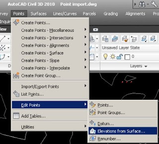
D. 將點位套疊並加入來自Google Earth地形的高程值,可以利用Point->Edit Point->Elevation from Surface選單來處理。If you want get the elevation value form Google Earth surface you can click the "Point->Edit Point->Elevation from Surface" from menu bar.

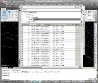
E. 之後點位資料就有來自Google Earth的高程值了。 Right now, you get the elevation form Google Earth Surface.

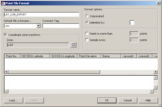
F. 最後就是將點位資料匯出為文字檔或其他格式作比對,方法就是建立一個新的點檔案格式,然後匯出。
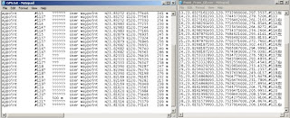
注意:筆者設定經緯度讀取的資料格式為DECDEG Latitude與DECDEG Longitude,讀者也可以改用其他格式的輸出。Finally you can export the Point data to CSV file. As well as, you can create another Point File Format for export.

成果比對如下,大至上Google Earth與GAMIN牌GPS軟體MapSource還是有些許差異,但是原則上高程值並沒有太大的誤差值。

操作心得:
1. 讀者可以利用這樣的範例練習Civil 3D點位資料的匯入與匯出,並且建立自己需要的格式。
2. 此外,還可學習到如何利用Civil 3D轉換測點座標至別的座標系統。
3. 可以學習如何利用測點攫取地面高程。
4. 這是一個衍生的應用,如果使用者缺依些資料(粗略的資料),就可以用Civil 3D與Google Earth來建立作為參考。